Design & Drawing: The Precise Translation of Vision into Engineered Reality
A plan establishes the vision—the what, the why, the how much. It defines objectives, quantifies requirements, and validates feasibility. But a vision, however compelling, cannot be built. It cannot be fabricated, installed, or commissioned. Between the strategic blueprint and the operational warehouse lies a critical bridge: detailed engineering design.
This is the phase where concepts become calculations, where layouts become dimensions, where requirements become specifications. It is the discipline of translating vision into precision—converting the abstract into the absolute, the approximate into the exact. Every beam that will bear a load, every weld that will secure a connection, every millimeter of clearance that will determine whether a shuttle passes or jams—all are defined during design.
KINGSHELVING approaches design and drawing with a fundamental conviction: precision is not an aspiration; it is an obligation. Our engineering team does not merely produce drawings; they produce instruction sets for reality—documentation so complete, so accurate, so unambiguous that the facility built from them performs exactly as the plan envisioned.
Core Positioning: The critical bridge between strategic planning and physical reality; the discipline that translates vision into precise, actionable engineering documentation.
Strategic Value: Converts concepts into calculations, dimensions, and specifications; defines every load path, every connection, every clearance with absolute precision.
KINGSHELVING Philosophy: Precision is not an aspiration—it is an obligation. Design produces not drawings, but instruction sets for reality.
I. The Design Imperative: Why Precision Defines Performance
The Cost of Imprecision
In automated warehousing, millimeters matter. A clearance assumed but not verified becomes a collision during commissioning. A load path calculated but not validated becomes a structural failure under peak stress. A dimension approximated but not specified becomes a field modification that delays go-live and inflates costs. The consequences of imprecise design cascade through every subsequent phase:
Procurement delays: Incomplete or ambiguous specifications require clarification, extending lead times and risking incorrect orders
Fabrication errors: Drawings that lack detail force fabricators to interpret, introducing variation and potential failure points
Installation conflicts: Unresolved interfaces between systems are discovered on site, requiring costly rework and schedule impacts
Commissioning failures: Systems designed without adequate tolerances fail to handshake, jam, or misalign, extending the path to operational readiness
Performance shortfalls: Designs not validated against actual operating conditions fail to achieve promised throughput, density, or reliability
The ROI of Precision
Conversely, investment in rigorous design delivers measurable returns:
Procurement confidence: Complete specifications enable accurate quoting, firm pricing, and reliable delivery commitments
Fabrication efficiency: Detailed drawings minimize interpretation, reduce errors, and accelerate manufacturing
Installation velocity: Resolved interfaces and coordinated systems enable smooth, continuous field assembly
Commissioning certainty: Designs that account for tolerances and handshakes reduce surprises and accelerate qualification
Operational reliability: Systems engineered with adequate margins perform predictably under all conditions, not just ideal ones
The Design Timeline
Design is not a single activity but a phased process that transforms conceptual plans into executable instructions:
| Phase | Purpose | Key Activities | Deliverables |
|---|---|---|---|
| Conceptual Design | Translate planning outputs into preliminary engineering solutions | System selection, layout development, high-level specifications | Concept drawings, equipment lists, preliminary specs |
| Detailed Engineering | Develop complete, fabrication-ready designs | Structural analysis, mechanical design, control system design | Detailed drawings, calculation reports, BOMs |
| Integration Design | Coordinate all systems into a cohesive whole | Interface definition, clash detection, sequence of operations | Integrated drawings, interface specifications |
| Construction Documentation | Produce documents for procurement, fabrication, and installation | Shop drawings, installation manuals, test protocols | Complete drawing package, specifications, test plans |
Imprecision causes procurement delays, fabrication errors, installation conflicts, commissioning failures, and performance shortfalls.
Precision delivers procurement confidence, fabrication efficiency, installation velocity, commissioning certainty, and operational reliability.
Design is a phased process: Conceptual Design → Detailed Engineering → Integration Design → Construction Documentation.
II. Conceptual Design: From Requirements to Solutions
System Engineering
Conceptual design begins with the translation of functional requirements into engineering solutions. KINGSHELVING’s engineers take the outputs of planning—throughput volumes, storage density targets, operational profiles—and determine the specific systems that will deliver them:
Storage system selection: Based on SKU profiles and throughput requirements, engineers select optimal storage technologies—single-deep selective, double-deep, push-back, drive-in, pallet shuttle, ASRS stacker, miniload, or combinations
Material flow definition: Engineers map the movement of goods through the facility—receiving to storage, storage to picking, picking to packing, packing to shipping—defining the sequence of operations and equipment interfaces
Equipment sizing: Preliminary sizing of all major systems—number of cranes, shuttle vehicles, conveyor zones, workstations—based on throughput modeling and simulation
Layout Development
Conceptual designs are translated into preliminary layouts that establish spatial relationships:
Zone definition: Clear delineation of functional areas—receiving, quarantine, storage, picking, packing, shipping, support spaces
Flow path design: Material paths optimized for distance, congestion avoidance, and process sequence
Equipment placement: Preliminary positioning of all major equipment—ASRS aisles, conveyor networks, workstations, lifts
Integration points: Identification of handoffs between systems—crane-to-conveyor, conveyor-to-workstation, workstation-to-sortation
Preliminary Specifications
For each major system, conceptual design produces high-level specifications that guide subsequent detailed engineering:
Performance requirements: Throughput rates, cycle times, accuracy targets
Operational parameters: Load weights, dimensions, handling characteristics
Environmental conditions: Temperature ranges, humidity, cleanliness requirements
Regulatory requirements: Applicable codes, standards, certifications
System engineering translates functional requirements into specific technology solutions—storage, flow, equipment sizing.
Layout development establishes spatial relationships, flow paths, and integration points.
Preliminary specifications define performance, operational, environmental, and regulatory requirements for each system.
III. Detailed Engineering: From Concepts to Calculations
Structural Engineering
The structural integrity of an automated warehouse depends on rigorous engineering of every load-bearing element. KINGSHELVING’s structural engineers analyze and design:
Racking systems: Upright frames, beams, bracing, connections—all engineered for specified loads, seismic conditions, and long-term durability
Load calculations: Dead loads (self-weight), live loads (stored product), seismic loads, wind loads (for exterior applications), and special loads (crane impacts, shuttle dynamics)
Seismic design: In seismic zones, structures are engineered to withstand specified ground motions through non-linear analysis, energy dissipation, and ductile detailing
Foundation interfaces: Connection details between racking and facility foundations—anchor bolts, base plates, grout specifications
Mechanical Engineering
Automated equipment requires precise mechanical design:
Crane and shuttle design: Structural analysis of moving equipment—masts, carriages, drive systems—under dynamic loading
Conveyor engineering: Roller spacing, belt tension, drive sizing, accumulation logic—all calculated for specific load profiles and throughput requirements
Workstation design: Ergonomic analysis, reach studies, lighting specifications—ensuring human operators can perform efficiently and safely
Lift and elevator engineering: Guide rail alignment, drive sizing, safety system design—ensuring reliable vertical transport
Control System Engineering
The intelligence that orchestrates automation requires equally rigorous design:
Control architecture: Definition of control hierarchy—centralized vs. distributed, PLC vs. PC-based, network topology
I/O definition: Inventory of all sensors, actuators, drives—type, quantity, location, communication protocol
Sequence of operations: Detailed description of how equipment should behave under all conditions—normal operation, exception handling, recovery
Safety system design: Integration of safety PLCs, light curtains, emergency stops—ensuring compliance with applicable safety standards
Software Engineering
The software that manages the warehouse must be designed with the same rigor as the hardware:
WMS/WCS architecture: Definition of software modules, data flows, integration points
User interface design: Screen layouts, workflows, user interactions—designed for efficiency and error reduction
Integration specifications: Detailed requirements for interfaces with ERP, WMS, and other enterprise systems
Testing requirements: Unit test, integration test, performance test, acceptance test specifications
Structural engineering ensures all load-bearing elements are designed for specified loads, seismic conditions, and long-term durability.
Mechanical engineering delivers precise design of moving equipment, conveyors, workstations, and lifts.
Control system engineering defines the intelligence layer—architecture, I/O, sequences, safety.
Software engineering designs the WMS/WCS architecture, user interfaces, integrations, and test requirements.
IV. Integration Design: Creating a Coherent System
Interface Definition
Automated warehouses are systems of systems. Integration design defines how they connect:
Mechanical interfaces: Physical connections between equipment—crane-to-conveyor handshakes, conveyor-to-workstation transfers, workstation-to-sortation feeds
Control interfaces: Communication protocols, signal definitions, timing requirements—ensuring equipment from different vendors can exchange information reliably
Software interfaces: API definitions, data structures, transaction sequences—ensuring WMS, WCS, and enterprise systems can communicate seamlessly
Electrical interfaces: Power requirements, connection points, grounding schemes—ensuring all equipment receives reliable, appropriate power
Clash Detection
In complex facilities, physical conflicts between systems must be identified and resolved before construction:
3D modeling: All systems modeled in three dimensions—racking, cranes, conveyors, workstations, building structure, MEP systems
Clash analysis: Automated detection of interferences—rack-to-structure, conveyor-to-column, crane-to-building
Resolution: Design modifications to eliminate clashes—adjusting positions, modifying routing, reconfiguring layouts
Validation: Confirmation that resolved designs maintain required clearances and operational envelopes
Sequence of Operations
Integration design produces a comprehensive description of how the facility should operate:
Normal operations: Material flow sequences under normal conditions—receiving, putaway, storage, picking, packing, shipping
Exception handling: How the system should respond to abnormal conditions—equipment failures, jams, misreads, quality holds
Recovery procedures: Steps to restore normal operation after exceptions—clearance sequences, restart procedures, manual intervention protocols
Mode management: Different operating modes—day shift, night shift, maintenance, peak season, emergency
Coordination with Building Systems
Automated warehouses must integrate with facility infrastructure:
Structural coordination: Load paths from equipment to building structure; deflection limits; expansion joints
Electrical coordination: Power distribution, panel locations, cable routing; backup power requirements
HVAC coordination: Temperature control requirements for equipment and product; heat dissipation calculations
Fire protection coordination: Integration with fire detection and suppression systems; compliance with applicable codes
Interface definition specifies mechanical, control, software, and electrical connections between systems.
Clash detection uses 3D modeling to identify and resolve physical conflicts before construction.
Sequence of operations defines normal operation, exception handling, recovery, and mode management.
Building coordination ensures integration with structure, power, HVAC, and fire protection systems.
V. Drawing Production: The Instruction Set for Reality
Drawing Types
KINGSHELVING produces a comprehensive set of drawings that serve as the definitive instruction set for procurement, fabrication, and installation:
| Drawing Type | Purpose | Content | Audience |
|---|---|---|---|
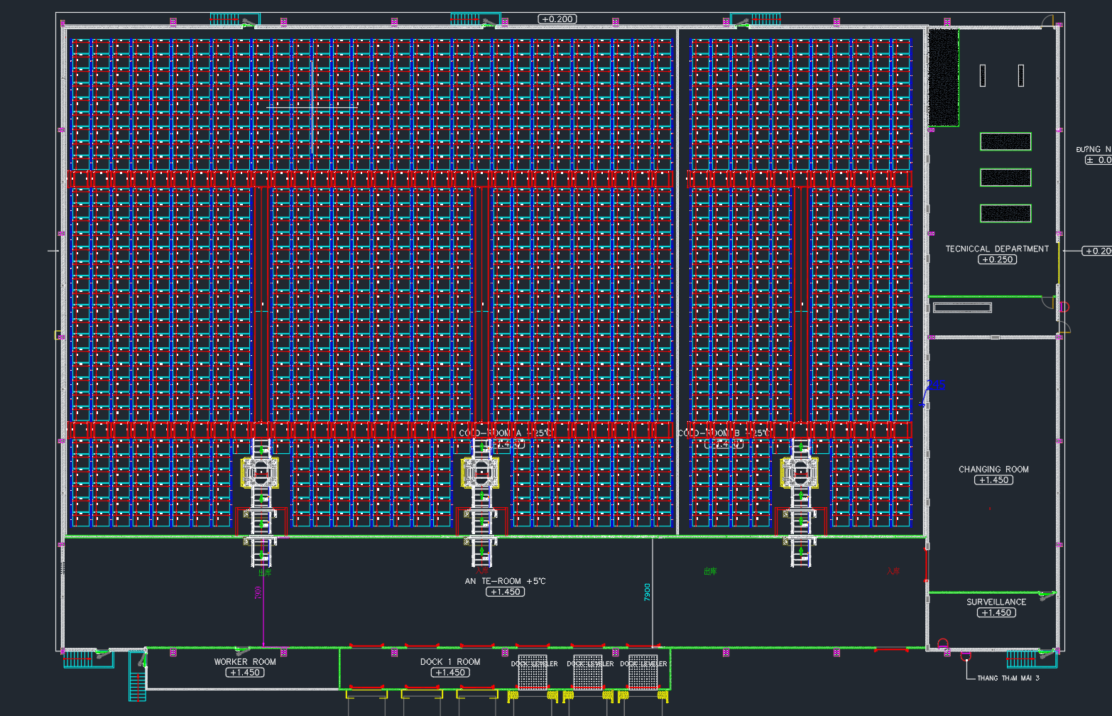
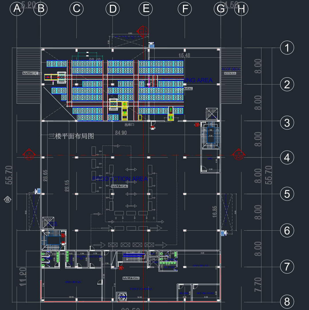
| General arrangement | Show overall layout and spatial relationships | Plan views, elevations, sections of entire facility | Project managers, installers, inspectors |
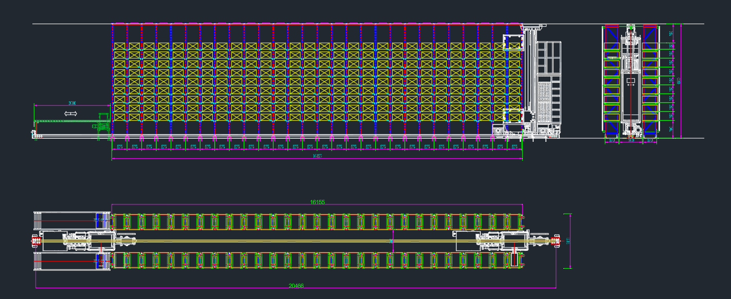
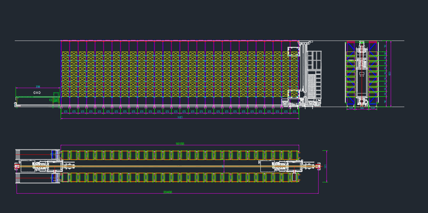
| Equipment drawings | Detail individual equipment items | Dimensions, connections, weights, installation requirements | Fabricators, installers |
| Structural drawings | Define racking and support structures | Member sizes, connections, anchor details, bracing | Steel fabricators, erectors |
| Mechanical drawings | Detail conveyors, lifts, workstations | Component locations, drive arrangements, clearances | Mechanical installers |
| Electrical drawings | Define power and control wiring | Panel layouts, cable routing, termination points | Electricians |
| Control drawings | Show control system architecture | PLC layouts, network topology, I/O assignments | Controls engineers, integrators |
| Installation details | Provide specific installation instructions | Anchor details, splice connections, alignment procedures | Field installers |
Drawing Standards
KINGSHELVING produces drawings to industry standards that ensure clarity and consistency:
CAD platform: Industry-standard CAD software (AutoCAD, Revit) with fully layered, organized drawings
Dimensioning: Clear, unambiguous dimensions with appropriate tolerances
Symbols and notations: Consistent use of industry-standard symbols and abbreviations
Revision control: Clear revision history, issue dates, and change descriptions
Title blocks: Complete project information, drawing numbers, approvals, and dates
3D Modeling and BIM
For complex projects, KINGSHELVING provides Building Information Modeling (BIM) deliverables:
3D models: Fully coordinated 3D models of all systems—racking, equipment, conveyors, workstations
Clash-free coordination: Models coordinated with building structure and MEP systems
Model uses: Quantity takeoffs, construction sequencing, facility management
Deliverables: Native model files, IFC exports, Navisworks models
Specifications
Complementing drawings, KINGSHELVING produces comprehensive written specifications:
Material specifications: Steel grades, finishes, coatings, fasteners
Equipment specifications: Performance requirements, component brands, warranty terms
Installation specifications: Procedures, tolerances, testing requirements
Quality requirements: Inspection criteria, acceptance standards, documentation
Drawing types include general arrangement, equipment, structural, mechanical, electrical, control, and installation details.
Drawing standards ensure clarity, consistency, and professional quality across all documentation.
3D modeling/BIM provides clash-free coordination, quantity takeoffs, and facility management data.
Specifications complement drawings with written requirements for materials, equipment, installation, and quality.
VI. Quality Assurance: Ensuring Design Integrity
Design Reviews
KINGSHELVING conducts structured design reviews at key milestones:
Conceptual design review: Stakeholder validation of proposed solutions before detailed engineering begins
Interim design reviews: Progress checks at 30%, 60%, and 90% completion points
Pre-release review: Final validation of complete design package before release for procurement or fabrication
Cross-discipline reviews: Engineers from structural, mechanical, electrical, and controls disciplines review each other’s work for coordination
Calculations and Analysis
Every design decision is supported by appropriate calculations:
Structural calculations: Load takedowns, member sizing, connection design, seismic analysis
Mechanical calculations: Drive sizing, torque requirements, speed profiles, acceleration limits
Electrical calculations: Load studies, voltage drop, cable sizing, protective device coordination
Thermal calculations: Heat loads, cooling requirements, insulation specifications
Peer Review
Critical designs undergo independent peer review:
Internal peer review: Senior engineers review designs before release
External peer review: For complex or critical projects, independent consultants review key design elements
Third-party certification: Where required by code or client, designs are certified by licensed professional engineers
Drawing and Document Control
KINGSHELVING maintains rigorous control over all design documentation:
Version control: Every drawing and document has unique version identifier; changes tracked and documented
Approval workflow: Formal approval process before release; electronic signatures and date stamps
Distribution control: Controlled distribution of issued documents; obsolete versions recalled or marked
Archive: Complete archive of all versions maintained for project history and future reference
Design reviews at key milestones ensure stakeholder alignment and design quality.
Calculations and analysis support every design decision with appropriate engineering rigor.
Peer review provides independent verification of critical designs.
Drawing and document control ensures version integrity, approval traceability, and distribution management.
VII. The KINGSHELVING Design Advantage
Integrated In-House Capability
Unlike design firms that specialize in a single discipline, KINGSHELVING maintains integrated in-house capabilities across all required engineering domains:
Structural engineering: Licensed professional engineers experienced in racking and steel structures
Mechanical engineering: Specialists in automated equipment design—cranes, shuttles, conveyors, lifts
Electrical engineering: Experts in power distribution, motor control, and industrial automation
Controls engineering: Programmers skilled in PLC, motion control, and safety systems
Software engineering: Developers who understand both warehouse operations and automation equipment
This integration ensures that designs are coordinated across disciplines, with no gaps between structural and mechanical, mechanical and electrical, electrical and controls.
Experience-Led Design
KINGSHELVING’s design team brings decades of accumulated experience to every project:
Thousands of installed systems: Designs benefit from lessons learned across hundreds of successful implementations
Real-world feedback: Field experience informs design improvements—what works, what fails, what can be optimized
Application knowledge: Deep understanding of diverse industries—food, pharmaceutical, automotive, e-commerce, cold chain
Technology expertise: Mastery of the full spectrum of ASRS technologies—stacker cranes, shuttles, conveyors, sorters
Constructability Focus
KINGSHELVING designs with construction in mind:
Installation sequences: Designs consider how equipment will be erected, aligned, and connected
Access for maintenance: Clearances and access paths designed for ongoing service and component replacement
Tolerance management: Realistic tolerances specified based on actual fabrication and installation capabilities
Field adjustment provisions: Designs include means for field adjustment where needed—shims, slotted holes, adjustable supports
Future-Adaptable Design
KINGSHELVING designs for the long term:
Expandability: Provisions for future expansion—additional aisles, extended conveyors, added workstations
Technology upgrades: Accommodation for future technology insertion—new shuttle models, upgraded controls
Process flexibility: Designs that can accommodate changing operational requirements—new SKU profiles, different throughput patterns
Obsolescence management: Selection of components with long lifecycle and available spares
Your Plan. Our Design. Reality, Precisely Engineered.
The automated warehouse that performs flawlessly on day one is not the product of luck or guesswork. It is the product of rigorous, detailed engineering—the systematic translation of vision into calculations, of concepts into dimensions, of requirements into specifications. Every beam that stands for decades, every shuttle that cycles millions of times, every handshake that never fails was first designed—meticulously, comprehensively, exactly.
KINGSHELVING’s design and drawing capability delivers that precision. It takes your validated plan and transforms it into the complete instruction set for procurement, fabrication, installation, and commissioning. It ensures that every component fits, every interface aligns, every sequence executes as intended. It bridges the gap between what you want and what you get—with zero ambiguity, zero interpretation, zero surprises.
When you entrust KINGSHELVING with design, you are not merely purchasing drawings. You are investing in certainty—the confidence that the facility built from these documents will perform exactly as the plan envisioned, from the first pallet on day one to the millionth cycle years later.
Your vision, our plan, KINGSHELVING design. Reality, precisely engineered.